

 |  |  |  |  |  |  |
|---|---|---|---|---|---|---|
 |
Projects
Hands-on experience is the best kind of experience. The following projects contain my designs and practice. The projects contain analog circuitry, sensors, C programming, and development tools application. Click on the images for more detail.


CSI Adapter board
I designed this 4-layer board as a helpful tool to test a specific camera module. This board is to interface the CM4IO CSI-2 port & GPIO pins to a separate camera module through an FPC. The FPC connectors are laid out this way to keep the differential signals on the same layer.
Superheterodyne FM Receiver
The FM receiver is set to the channel 88.1MHz and outputs signal to speaker. The receiver utilizes the SA605 IC which includes 2 mixers and 2 amplifiers. I designed the front end (RF filter, LNA, image rejection filter), oscillator, and the demodulation with matched impedance's.


Colpitts Oscillator
The 2MHz oscillator is implemented with a tank circuit and tapped capacitor feedback. The amplifier is an active BJT and is loaded with a common collector. The circuit was made in a dead bug fashion.
Solar Simulator
The solar simulator replicates the wavelength spectrum, irradiance, and uniformity of the sun rays within the atmosphere (AM0) using a hybrid approach of high power LEDs and tungsten lamps. The light sources are driven by a voltage controlled current sources and are supplied with boost converters. The device can be used to simulate spacecraft orbit and measure photovoltaic characteristics.


MPPT and Charge Control
As part of the Cubesat program at UCSC, I contributed to the Electrical Power System. I designed the energy transfer from Solar panels and storage to Lithium-ion batteries.
2.0kHz Infra-Red Detector
The circuit indicates when the infra-red sensor is pointing at the direction of a 2kHz infrared emitter that is at most 5.5 meters away. The circuit is implemented with transimpedance amplification, non-inverting amplifiers, multi feedback filters, an envelope detector, and a Schmidt trigger. The circuit was used in a robotics competition to detect an enemy robot.


Cadence Handset PCB
Designed PCB of a wireless car handset using Cadence orCAD and PCB Editor
Track Wire Detector
The circuit indicates when the sensing inductor is at most 4 inches away from a 25kHz alternating magnetic field. The circuit is implemented with non-inverting amplifiers, multi feedback filters, an envelope detector, and a Schmidt trigger. The circuit was used in a robotics competition to avoid obstacles emitting the signal.


Slug Game FPGA
A slug crossing game only utilizing logic gates within an FPGA. Flipflops save the position of the game objects and the pixel on the VGA display. Logic is programmed in Verilog.
Metastability Experiment
The experiment analyzes the instability at the output of a flip flop when the data input does not provide enough setup time before the clock. The circuit is designed to evaluate this phenomenon. Delays, transmission lines, and impedance matching is considered for logic and testing equipment.


Attitude Control Algorithm
Programmed an Attitude Heading Reference System (AHRS) on a microcontroller using a gyroscope, accelerometer, and magnetometer (9DOF IMU) sensors. The sensors are calibrated and implement a rotation matrix.
Capacitive Touch Sensor
Two methods to sense human touch. Both methods use an RC filter and 555 timer. The analog approach uses a differential amplifier to amplify the phase difference. A software approach measures the frequency change from the 555 timer.


Cadence Charger PCB
Used Cadence orCad and PCB designer to manufacture charger.
Piezo and Flex Sensor Instrument
The audio frequency output is correlated to the stress angle of the flex sensor and intensity is raised after every piezo contact. I program a microcontroller using C to linearize the nonlinear characteristics of the sensors.


LED Matrix
56 by 5 LED matrix that can display words and images. LEDs are controlled by shift bit registers and microcontroller. The LEDs are driven by MOSFET current sources. The text output is programmed in C using bit operators.
LED Dice
"Randomly" generates a dice number with LEDs. The random generation is provided by the high-frequency output of the 555 timer. The dice number is created with the logic of a decade counter and BJT drivers.
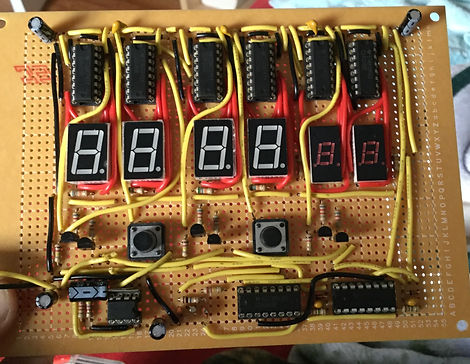
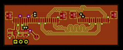
Clock
Uses a quartz crystal and frequency dividers to generate a second. The second is passed on asynchronously to 7 segment drivers with counters (CD 4026 IC).